This post is about a simple circuit to test crystal oscillators . They are found in most
of the RF and processing circuitry as an external component to provide
clocking, time reference for synchronization of internal system
operations. testing them isn't that straight forward by connecting its terminals to a multimeter or an oscilloscope. This
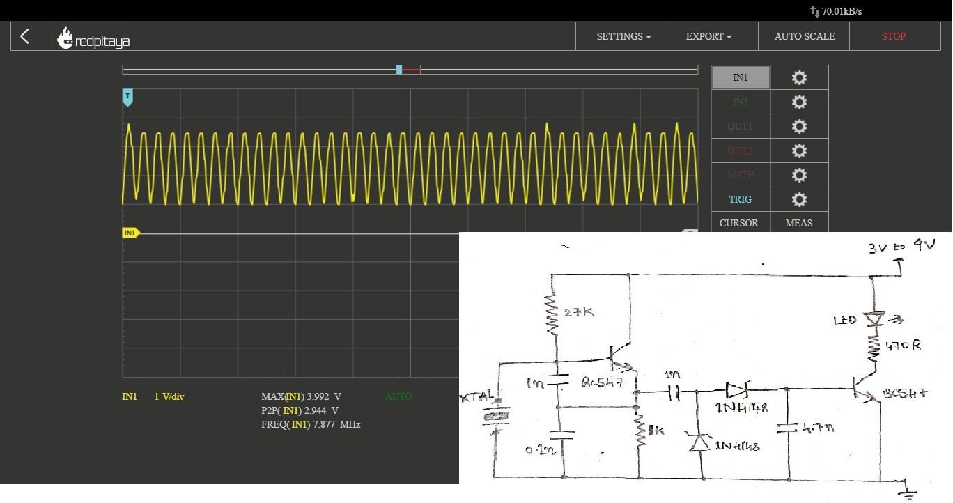
is an interesting test circuit for crystals in 1MHz - 30MHz range with 2
NPN transistors, Zeners, some passives, and thought of testing a few
crystals.
When the DUT crystal
oscillates, the signal passes through the 1nF loading capacitor to the
two Zeners, thereby charging the 4.7nF capacitor and turns on the second
transistor which in turn illuminates the LED, indicating that it's all
good!
Comments
Post a Comment