What Is Direct Memory Access (DMA)?


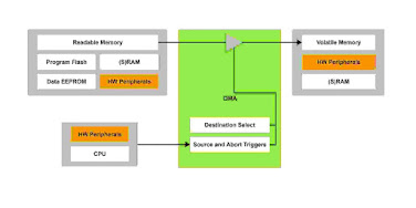
Direct Memory Access (DMA) is a feature of computer systems that allows hardware subsystems to access main system memory (RAM) independent of the Central Processing Unit (CPU).

The Direct Memory Access (DMA) hardware peripheral on PIC® microcontrollers (MCUs) allows for direct memory-to-memory mapping and multitasking behavior through concurrent operation of the DMA and the CPU. This enables more flexible usage of eXtreme Low Power (XLP) technologies through core-independent movement of data in low-power modes and significant improvements in data throughput and latency.


Why Is DMA Used?


Most CPU operations in MCU-based systems involve the movement of data. In many cases, this can significantly limit the throughput and responsiveness of a system. For example, an interrupt can cause the CPU to stop what it is currently doing to service the interrupt. In low-power applications, this can significantly increase overall power consumption.

The DMA provides a method of offloading data movement operations from the CPU, allowing for concurrency and true multitasking behavior in the system. This ultimately reduces interrupt latency, thereby improving system responsiveness and power consumption. The DMA peripheral can move data through two methods:

  • Moving data while the CPU clock is disabled (e.g. low-power modes and XLP technology)
  • Utilizing unused CPU cycles that occur when the CPU is idle or waiting for an event

How Is DMA Used?


Configuration Context Switching

Having multiple configurations of peripherals can greatly expand the functionality of a device and lowers unit costs as well as overall BOM cost. However, changing configurations can be CPU intensive as the registers and configuration bits for peripherals need to be completely altered, which could bring about performance issues in some applications.

The DMA allows for more efficient and robust context-based configuration through a combination of customizable software- and hardware-based triggers that permit automated context-based device configuration independent of the CPU.

System Automation

The DMA peripheral can be used to automate any system process involving data transfer. This includes the management of state machine implementations and reconfiguration of other Core Independent Peripherals (CIPs), providing you with an efficient method of using a single peripheral in a variety of ways in response to hardware- or software-defined triggers.

Additionally, loop-based processes can be automated due to the recursive nature of calling and processing data, drastically accelerating the throughput of the device, and by extension, your system.

Arbitrary Waveform Generation

Many applications require arbitrary waveform data, which can be difficult to manage with a software-centric system. Arbitrary waveforms are traditionally generated using complex Digital Signal Processing (DSP) techniques that require high-end and expensive devices, large amounts of computation and loads of code.

The DMA can be used to create these same arbitrary waveforms by reading data sequentially from memory in the form of a lookup table and feeding this to other peripherals such as a Pulse-Width Modulator (PWM).


Comments

Popular posts from this blog

What is the ESP32 VSPI / HSPI

 The ESP32 integrates four SPI peripherals. SPI0 and SPI1 are used to access the ESP32’s attached flash memory and thus are currently not open to users to be used . They share one signal bus via an arbiter. SPI2 and SPI3 are general purpose SPI controllers, sometimes referred to as HSPI and VSPI, respectively. They are open for use. SPI2 and SPI3 have independent signal buses with the same respective names. Each bus has three CS lines to drive up to three SPI slaves.  

Most common baud rates table

  The following table shows the most used baud rates. The left side part of the table shows speed and bit duration. The right part shows real transmission speed assuming there is no parity, 8 data bits and one stop bit.   Bauds Bits/s Bit duration Speed Actual speed Actual byte duration 50 bauds 50 bits/s 20.000 ms 6.25 bytes/s 5 bytes/s 200.000 ms 75 bauds 75 bits/s 13.333 ms 9.375 bytes/s 7.5 bytes/s 133.333 ms 110 bauds 110 bits/s 9.091 ms 13.75 bytes/s 11 bytes/s 90.909 ms 134 bauds 134 bits/s 7.463 ms 16.75 bytes/s 13.4 bytes/s 74.627 ms 150 bauds 150 bits/s 6.667 ms 18.75 bytes/s 15 bytes/s 66.667 ms 200 bauds 200 bits/s 5.000 ms 25 bytes/s 20 bytes/s 50.000 ms 300 bauds 300 bits/s 3.333 ms 37.5 bytes/s 30 bytes/s 33.333 ms 600 bauds 600 bits/s 1.667 ms 75 bytes/s 60 bytes/s 16.667 ms 1200 bauds 1200 bits/s 833.333 µs 150 bytes/s 120 bytes/s 8.333 ms 1800 bauds 1800 bits/s 555.556 µs 225 bytes/s

How to program 8051 based MCU using Ptroteous Schematic capture and Source code editor to use timers using AT892051 + project files

 This tutorial is dedicated to use a 8051 based Microcontroller core and program it using keil's C51 tools on the Proteus Source code editor.  1- Brief History of 8051 one of the first microprocessors 4004 was invented by Intel Corporation as well as  8085 and 8086 microprocessors back in 1981,shortly after Intel introduced an 8-bit microcontroller called the 8051 . It was referred to as system on a chip because it had 128 bytes of RAM, 4K byte of on-chip ROM, two timers, one serial port, and 4 ports (8-bit wide), all on a single chip. When it became so widespread, Intel allowed other manufacturers to make and market different flavors of 8051 with its code compatible with 8051. It means that if you write your program for one flavor of 8051, it will run on other flavors too, regardless of the manufacturer. This has led to several versions with different speeds and amounts of on-chip RAM. 2- Features of AT892051 Microcontroller Compatible with MCS®-51Products 2K Bytes of R